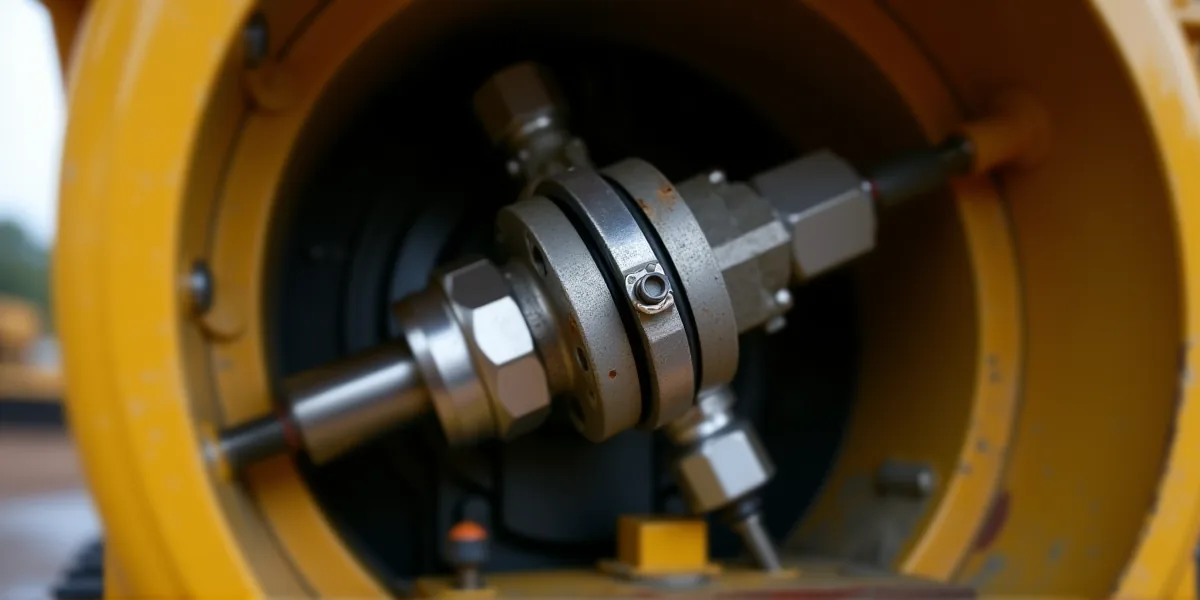
Introduction: The Silent Guardian of Your Hydraulic System
Hydraulic pressure sensors are often the most overlooked components on your excavator, wheel loader, or dozer. They sit quietly on the main pump or control manifold, converting mechanical pressure into an electrical signal that your machine’s Engine Control Module (ECM) relies on to make real-time decisions. These sensors manage everything from load-sensing functions to maximum system pressure limits and overload protection. When they work correctly, your machine responds crisply and efficiently. When they fail, the consequences can be severe: loss of digging power, false derates that shut down your machine in the middle of a job, or hidden pressure spikes that quietly destroy expensive pumps, valves, and hoses. Understanding how to maintain these sensors is not just about preventing downtime; it is about protecting the integrity of your entire hydraulic circuit.
Understanding How Pressure Sensors Work
Most mobile Hydraulic sensors are pressure transducers that output a voltage signal, typically ranging from 0.5V to 4.5V, powered by a stable 5V reference supply from the controller. The core of the sensor is a thin stainless steel diaphragm that flexes under hydraulic pressure. This flexure changes the electrical resistance or capacitance inside the sensor, which the ECM interprets as a specific pressure value. The controller uses this feedback loop constantly. If the sensor says the pressure is too high, the ECM might reduce pump displacement to save energy or prevent damage. If the sensor reads low, the pump may spool up to compensate. Because this component is the "eye" of your hydraulic system, any error in its reading leads directly to incorrect machine behavior. It is critical to note that these sensors are precision instruments, not just generic electrical parts. They must match the specific pressure range and voltage scaling of your machine’s hydraulic design.
Common Failure Modes and Symptoms
Identifying a bad sensor early can save you from a catastrophic pump failure. The most common issue is diaphragm fatigue or zero-shift. Over thousands of hours, repeated pressure spikes and vibration cause the internal diaphragm to deform. Once this happens, the sensor no longer reads the baseline value at zero pressure, creating a constant offset error. You might notice the machine feels sluggish or that the pressure gauge on the dashboard does not match a manual test. Another frequent problem is a blocked pressure port. Sludge, varnish, or metal wear debris can plug the tiny inlet or snubber orifice. This traps pressure inside the sensor, causing readings to stay stuck high or respond slowly when the load changes. This often follows a period of high Hydraulic contamination. Electrical issues are also prevalent. Connectors near pumps and manifolds are exposed to oil mist, moisture, and vibration. Corroded pins or oil ingress create intermittent connections, leading to erratic jumping readings and random fault codes. Finally, physical damage to the wiring harness is a major culprit. If the cable rubs against sharp frame edges or moving hoses, the insulation wears away. This can cause short-to-ground faults, locking the reading at the minimum or maximum scale, which confuses the ECM and disables protective functions.
Inspection and Diagnostic Procedures
Before touching the sensor, always follow lockout/tagout procedures. Shut down the engine, relieve Hydraulic pressure, lower implements, and allow the oil to cool. A visual inspection should be part of your daily pre-shift routine. Check the dashboard for erratic pressure readings or active fault codes. Look for oil weeping at the sensor’s mounting boss, which indicates a compromised seal. During your 250-hour service, physically inspect the sensor. Clean mud and oil residue from the electrical connector and check the wiring harness for chafing. Gently wiggle the connector while monitoring live data on the display; if the pressure reading jumps or freezes, you have an intermittent connection fault. For a definitive diagnosis, you need to test the sensor electrically. Disconnect the wiring connector and use a digital multimeter. With the key on, check the harness side for the 5V reference voltage and continuity back to the ECM. Then, measure the sensor’s output. If the machine is cold and static, the voltage should correspond to the zero-pressure baseline. If you see infinite resistance, an open circuit, or a voltage that does not change with engine speed or load, the sensor is likely failed. Cross-verifying with a manual pressure gauge on the same port is the gold standard for confirming sensor accuracy.
Replacement Best Practices
When replacing a Hydraulic pressure sensor, do not cut corners. Use an OEM or high-quality equivalent part that matches the exact pressure range and voltage scaling of the original. Installing a sensor with the wrong range is a common error that leads to improper pump control. Before installing the new unit, clean the mounting port thoroughly to remove any debris that could block the new sensor’s inlet. Apply thread sealant compatible with hydraulic fluid to the threads, but be careful not to get sealant inside the port. Torque the sensor to the manufacturer’s specification. Over-tightening can crush the internal O-ring or crack the sensor body, leading to leaks. Under-tightening causes oil weepage. After installation, clear any existing fault codes from the ECM. Run the machine through a full warm-up cycle and perform heavy load operations to verify that the pressure readings are stable and accurate. If errors persist after replacing the sensor, do not immediately blame the new part. Inspect the wiring, connectors, and even the ECM, as the fault may lie elsewhere in the circuit.
Preventing Contamination and Electrical Damage
Preventive maintenance is far cheaper than reactive repair. Keep the area around the sensor clean. Oil and dirt can attract moisture, accelerating corrosion on the connector pins. Apply dielectric grease to clean connector pins after any service to block out moisture and oil. Protect the wiring harness with rubber grommets and secure clips to prevent chafing against sharp edges or vibrating hoses. Monitor your hydraulic oil condition through regular sampling. Oxidized oil creates varnish, which can clog the sensor’s pressure port. If you find varnish in your oil samples, clean the sensor port and consider flushing the system. Additionally, respond immediately to high-pressure alarms. Do not disable overload protection to keep working. A pressure spike that damages the sensor diaphragm is often a symptom of a deeper issue, such as a stuck valve or a failing pump, that needs to be addressed. Keep detailed logs of pressure readings and fault codes. Tracking trends over time allows you to spot rising pressures or sensor drift before they lead to a complete failure.
Conclusion
Hydraulic pressure sensors are small, inexpensive components that play a disproportionately large role in your machine’s performance and longevity. By understanding their function, recognizing the signs of failure, and following rigorous inspection and replacement protocols, you can avoid the costly downtime associated with hydraulic failures. Treat these sensors with the same respect you give to your pumps and valves. Regular testing, proper installation, and protection from electrical and mechanical abuse will ensure that your hydraulic system remains responsive, efficient, and safe for years to come.