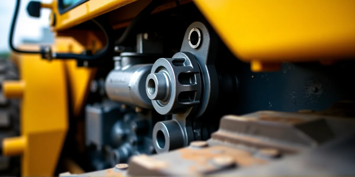
Hydraulic Oil Water Sensor Maintenance: A Practical Guide for Heavy Equipment
Water in hydraulic oil is one of the most insidious enemies of heavy machinery. It breaks down additives, causes rust on cylinder rods, and creates pitting on pump pistons and motor gears. To catch this before it becomes a catastrophic failure, many modern excavators, wheel loaders, and dozers are now equipped with online water content sensors. These devices, typically capacitive water activity probes, sit in the bypass sampling loop or reservoir and send real-time data to the machine’s Electronic Control Module (ECM). However, just like any other precision component, these sensors are not maintenance-free. They are sensitive to the harsh environment of a construction site. If you ignore the basics of sensor care, you risk getting false alarms that waste your time or, worse, missing a genuine water intrusion that will destroy your hydraulic system. Here is how to properly maintain, test, and interpret your hydraulic oil water sensors to keep your equipment running smoothly.
Understanding the Sensor and Why It Fails
Most modern water sensors measure "water activity," which is the percentage of saturation in the oil, rather than just parts per million (ppm). This allows the system to detect water before it reaches the saturation point where free droplets form. Because these sensors rely on dielectric properties, they are highly sensitive to chemical changes in the oil. The most common issue technicians face is not a broken sensor, but a dirty one. As hydraulic oil ages, it oxidizes. This creates varnish and sludge that can coat the capacitive polymer sensing film. If conductive metal wear particles or sludge build up on this film, the sensor interprets the change in electrical properties as high water content. This often happens after a pump or motor starts to wear, releasing debris into the circuit. Additionally, air entrainment from low oil levels or clogged tank breathers can cause turbulent flow, leading to noisy, fluctuating readings that are often mistaken for a faulty unit.
Regular Inspection Routines
Consistent inspection is the only way to distinguish between a sensor error and a real Hydraulic problem. Always follow lockout/tagout procedures: shut down the engine, relieve hydraulic Pressure, and let the oil cool before opening any lines.
Daily Pre-Shift: Check the dashboard or diagnostic tool for water saturation alarms. Look for erratic jumping values or frozen readings. Visually inspect the Sensor body and bypass sampling lines for any signs of oil leaks. A leak here can allow water to enter the sensor housing or oil to contaminate the electrical connections.
250-Hour Service: This is your checkpoint for physical integrity. Clean mud, oil, and salt residue from the electrical connector. Oil wicking into connector pins is a leading cause of intermittent signal dropout. While you are there, inspect the bypass tubing for kinks, abrasion, or loose fittings. A kinked tube restricts flow, preventing the Sensor from seeing a representative sample of the oil. Finally, check the small inlet pre-filter on the bypass line. If this is clogged, the sensor will give lagging or unstable data. Clean or replace it as needed.
1,000-Hour / Annual Service: Retrieve stored fault codes from the ECM. Verify that the bypass flow rate matches the OEM specification. At this stage, you should also compare the sensor’s live reading against an offline laboratory oil sample. If the sensor says 10% saturation but the lab test shows 0.5%, the sensor is likely fouled or drifting. Inspect the probe area for varnish buildup and apply dielectric grease to the connector pins to seal out moisture.
Testing and Diagnostic Procedures
When a water alarm trips, do not immediately replace the sensor. Follow these steps to isolate the issue:
1. Visual and Connector Check: Inspect the connector pins for corrosion, bent terminals, or oil contamination. Clean them with electrical contact cleaner. Ensure the bypass tubing flow direction matches the markings on the sensor.
2. Power and Continuity Test: With the ignition on and engine off, verify the sensor supply voltage (typically 5V or 24V DC). Check ground continuity to the chassis and ECM. Test for shorts between signal, power, and ground. A shorted wire can mimic a high-water alarm.
3. Bypass Flow Verification: Measure the flow through the bypass loop. Most sensors require a specific, stable flow rate. If the flow is too low due to a clogged pre-filter, the probe won’t get a good sample. Adjust restrictor valves if necessary to stay within the manufacturer’s operating window.
4. Live Comparison Test: Run the machine at normal operating temperature under a steady load. Record the online water saturation percentage. Simultaneously, collect a representative oil sample from the return line while the machine is running. Send this sample to an accredited fluid analysis lab. If the lab result is significantly lower than the sensor reading, the sensor cell is likely fouled with varnish or conductive debris.
5. Bench Calibration (Off-Machine): If you remove the sensor, flush the probe with certified clean reference oil of known water content. The reading should drop to near-zero or match the reference value. If it remains high after flushing, the sensing film is permanently degraded or coated with baked-on varnish.
When to Replace the Sensor
Replacement is necessary when the sensor can no longer provide accurate data, but only after you have ruled out other causes. Replace the unit if:
- The sensing film is permanently coated with baked varnish or conductive sludge that cannot be cleaned, causing consistent large deviations from lab results.
- The sensor fails power and signal tests after you have already ruled out wiring and connector faults.
- The internal capacitive element has degraded and cannot be recalibrated to OEM accuracy.
- The sensor housing or threads are cracked, causing persistent leaks into the electrical components.
When installing a replacement, use an OEM or high-quality equivalent with the correct output signal (CAN bus or 4-20mA) and temperature compensation range. Install new O-rings and torque the fittings to specification. After installation, clear fault codes, verify bypass flow, and cross-validate the new reading with a fresh lab oil sample. If the new sensor still reads high, troubleshoot the oil condition and bypass plumbing before blaming the hardware again.
Best Practices for Oil Quality Monitoring
To get the most out of your water sensor and protect your hydraulic system, adopt these monitoring habits. First, always maintain the bypass inlet pre-filter; it is the first line of defense against debris scratching the sensor. Second, aggressively eliminate air entrainment by keeping oil levels correct and servicing tank breathers, as air bubbles distort readings. Third, never rely on the sensor alone. Combine online data with regular laboratory oil analysis. The sensor tells you about water activity, but the lab test reveals viscosity, oxidation, and additive depletion. Finally, track trends rather than isolated readings. A gradual rise in water content might indicate a slow leak or condensation issue, while a sudden spike could mean a hose burst or a major seal failure. By logging these values alongside temperature and particle counts, you can predict component failure before it leads to downtime.
Conclusion
Hydraulic oil water sensors are valuable tools, but they are only as good as the maintenance behind them. By treating them as part of your regular inspection routine—cleaning connectors, checking bypass flow, and validating data against lab tests—you can avoid costly misdiagnoses. Remember, the sensor is a monitor, not a fixer. It alerts you to a problem, but proper hydraulic hygiene and timely oil changes are what actually keep your equipment healthy.